For any tech enthusiast, understanding the intricacies of a USB connector schematic diagram is key to establishing the data transfer between two electronic devices. Also known as a USB-A connection, this type of connector is used to power and connect peripherals, such as video game controllers or external hard drives.
Usb is one of the most popular and widely compatible connection types available, allowing for fast and efficient data exchange and power transfer. Its ability to quickly sync up with different devices makes it the go-to choice for many users.
However, the USB connector schematic diagram is complex, and understanding the different types and diagrams can be fairly challenging. The basics of the diagram include an array of wires that connect one device to another, transferring both data and power at certain voltages. Depending on the complexity of the device, the wiring patterns will vary.
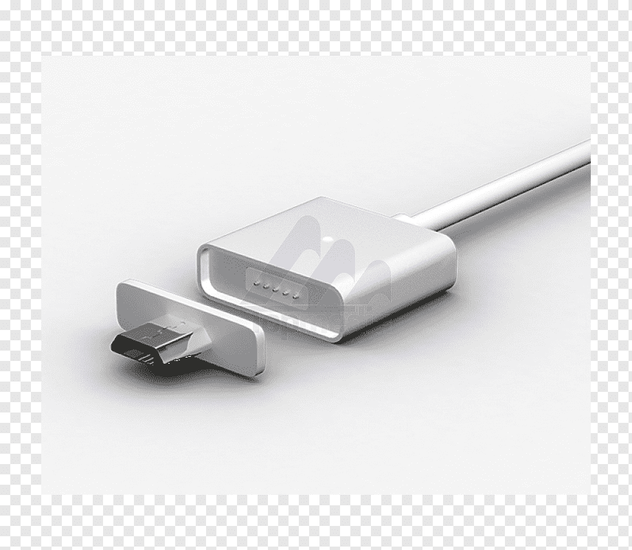
One of the key components of any USB connector schematic diagram is the ports – plugs (male connectors) and jacks (female connectors). Plugs have five pins that connect to a port’s five holes, while jacks receive the connection from the plug. From there, the current will flow in the correct direction, enabling the transmission of data and power.
The USB connector schematic diagram is also made up of additional components like terminal blocks, resistors, and capacitors. Each of these components work together to stabilize the current flow and prevent power surges or short circuits.
The USB cable itself utilizes twisted wires to reduce interference. This reduces the amount of static electricity generated by the cable, making it safer and more reliable.
Depending on the device, there are also several different types of USB cables available. In order to ensure full compatibility between two devices, it’s important to select the right type of cable for the application. This is where a basic knowledge of the USB connector schematic diagram comes in handy.
For any tech enthusiast, understanding the USB connector schematic diagram is key to building and maintaining any electronic device or data transfer system. It’s an essential aspect of the technological world, and a valuable asset for anyone seeking to learn about electronics.

Battery Charger Micro Usb Wiring Diagram Data Cable Angle Electronics Electrical Wires Png Pngwing

Samsung Galaxy Tab 2 Pinout Electrical Cable Wiring Diagram Usb Headphone Electronics Wires Schematic Png Pngwing

Circuit Diagram Of The Usb Power Adapter Scientific

Car Dock For Htc Mobile Phones

Kinect Xbox 360 Controller Usb Wiring Diagram Wires Angle Electronics Text Png Pngwing

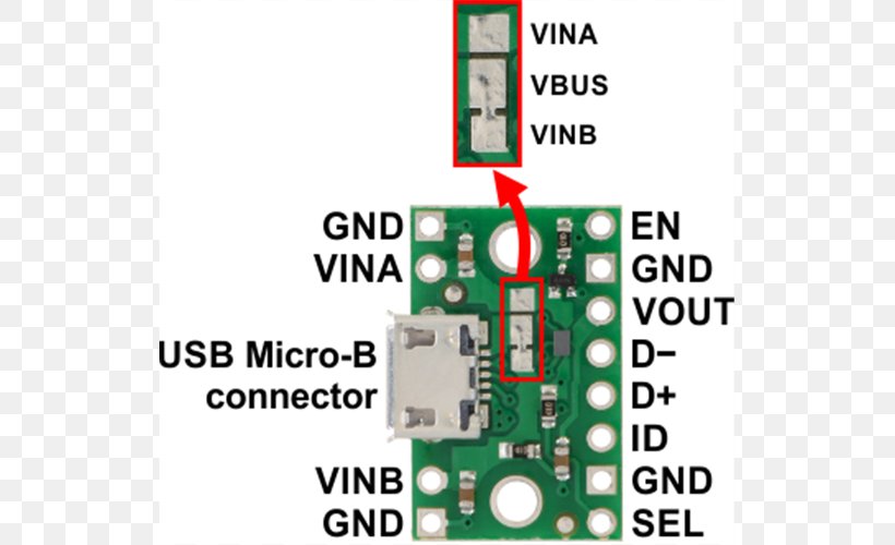
Pololu Fpf1320 Power Multiplexer Carrier With Usb Micro B Connector Schematic Diagram

Circuit Diagram Of The Usb Power Adapter Scientific

Pinout Micro Usb Wiring Diagram Mini Png 700x500px Area Circuit Component Computer Data
Guide How To Solder Your Own Usb2 0 3 Cables Overclock Net

Systems Analysis Of The Apple Lightning To Usb Cable Techinsights
Tf101g Charger Cable Broke Need Urgent Alternative Xda Forums

Usb Cable Pin Factory 54 Off Www Ingeniovirtual Com

Connector Pinouts

Power Supply Of The Phone Via Usb Pinout Micro Charging Connector
.jpg?strip=all)
Usb C Cable Wiring Diagram P Shine Electronic Tech Ltd

Usb Port Connection Online 52 Off Www Ingeniovirtual Com

Usb Hub Circuit Electronics Projects Circuits

Nokia N60 N70 N90 N91 N93 E70 E61 E62 E60 E50 3155i 6680 6681 7600 7700 7710 9300 9500 Pop Port Dku 2 Ca 53 Usb Cable Schematic Pinout Diagram Pinoutguide Com
Connector Basics Learn Sparkfun Com