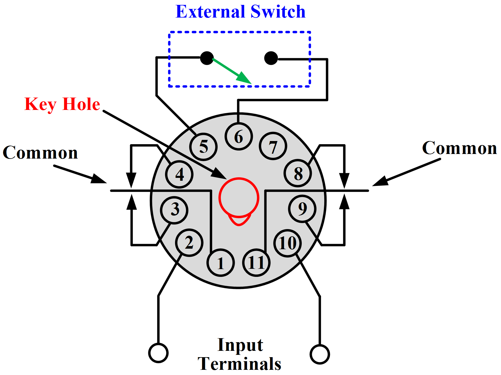
When it comes to electrical wiring, timing relays are an essential component. They provide a way of controlling and managing machinery and equipment by controlling when and how long a circuit is energized. For example, if you need to control the lights or pumps in your home or business, then timing relays can help ensure that the switch is off at the right time - saving you time, money, and hassle.
Timing Relay Wiring Diagrams provide a visual overview of which components are connected, and how they interact. This diagram clearly shows what pieces connect together, and when, in order to create a secure electrical system. Additionally, these diagrams provide an easy way to troubleshoot problems with your wiring.
To use a Timing Relay Wiring Diagram, start by locating the main electrical schematic, then locate the device you’ll be connecting the timer relay to. Once you have identified the device, it’s time to begin laying out the connections on the diagram.
Begin by connecting the load. Connect each of the three terminals; usually labeled A1, A2, and A3 to their respective points. Most relay wiring diagrams will provide a box-like symbol at each contact point, so you can easily tell which wire connects to which.
Next, connect the power source - this is normally the incoming power source - to the input terminals marked as B1 and B2. From here, connect the output terminals of the relay - usually designated as C1, C2, and C3 - over to the device. In some cases, the output terminals may need to be connected to multiple devices. If this is the case, make sure each connection is neatly labeled for easy reference.
Finally, if you plan to add any additional relays, such as a time delay relay, connect them according to the diagram. This will ensure that all components are correctly connected and operating as desired.
Timing Relay Wiring Diagrams are an invaluable asset when constructing and troubleshooting electrical systems. They enable you to easily lay out your connections and make any necessary adjustments. Additionally, they help prevent costly errors and malfunctions that occur when wiring components incorrectly. With a clear, concise Timing Relay Wiring Diagram, you can quickly and easily build a safe and reliable electrical system.

Time Delay Relay On Timer Off Electrical Academia

Time Delay Relay On Timer Off Electrical Academia

Time Delay Relay Basics Circuit And Applications
326 327 Series Time Delay Relays On Struthers Dunn

Time Delay Relay Basics Circuit And Applications

Time Delay Relays To Cycle A Traffic Signal Macromatic Controls Inc

Time Delay Electromechanical Relays Worksheet Digital Circuits

Solid State Timer Relay Electrical Academia
Multi Functional Timer Relay

Time Delay Electromechanical Relays Worksheet Digital Circuits

Scotsman Replacing The Electro Mechanical Timer And Switch With A Time Delay Relay 17 3355 01

Ics Time Delay Module Applications And Wiring
Delay Timer Wiring Cr4 Discussion Thread
Omron Twin Timer Relay Battery Driven Fuel Pump All About Circuits

Time Delay Relay Module Digital Lcd Display 6 30v Control Timer Switch Trigger Cycle For Smart

True Off Time Delay Relay Operation Macromatic Controls Inc

Time Delay Relay Basics Circuit And Applications

Transistor Timer

Circuit Diagram For The Delay Timer Scientific