Most of us strive to make our homes as energy efficient and cost effective as possible. Installing a time delay switch can help you save both money and energy by controlling the power used when switching on appliances. But before you start wiring, it's important to understand how time delay switch wiring diagrams work.
Time delay switches are designed to control the number of hours that electricity is used in a particular appliance. The switches are programmed to turn off the power at a specific preset time, reducing the amount of energy needed to operate the appliance. Most importantly, they help you avoid wasting electricity by running the appliance after it has already been switched off.
When wiring a time delay switch, it is important to follow the manufacturer’s instructions and diagrams included with the product. A typical time delay switch wiring diagram consists of two diagrams – the power diagram and the switch diagram. The power diagram shows the power supply connections, the switch diagram shows the switch wiring connections.
The power diagram provides information about the input voltage, current rating, and other power-related specifications. It also shows the type and size of fuses and how they should be connected. The diagram also indicates whether the switch uses AC or DC power.
The switch diagram shows how to connect the time delay switch to the load, such as the appliance being controlled. This includes the type and size of switch, as well as the type and size of the contactor if the switch is installed in an area with a large electrical load. The diagram also shows the wire colors used to make the connection between the switch and the load.
Understanding the diagrams provided in the installation manual is essential for correctly wiring a time delay switch. If you have any doubts or questions regarding your wiring, consult the manufacturer or a licensed electrician. Doing so will help ensure that the time delay switch is installed safely and correctly, saving you time, energy, and money in the long run.

Simple Delay Timer Circuits Explained Homemade Circuit Projects

Time Relay Delay Manufacturer From China Alion

Circuit Diagram For The Delay Timer Scientific

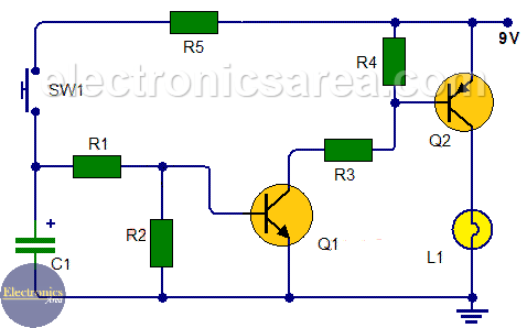
Time Delay Light Switch Circuit Using Transistors Electronics Area

Ics Time Delay Module Applications And Wiring

555 Timer Delay Off Circuit Diagram Eeweb

Time Delay Electromechanical Relays Worksheet Digital Circuits

Circuit Diagram For The Delay Timer Scientific

30 Minute Timer Circuit Using 555 Ic And 7555

On Delay Timer Circuit Diagram With Relay Using Capacitor

Time Delay Electromechanical Relays Worksheet Digital Circuits

Time Delay Electromechanical Relays Worksheet Digital Circuits

5 20 Minuts Timer Circuit Using Ic 555 Eleccircuit Com

Mzl 1024 24v Ignition Sensing Delay Timer Acdc Industries

Types Of Timer Circuits With Schematics And Its Working Principle

Air Circuit Breakers Akh Aks Akn Series Accessories Uvt Time Delay Controller Udc Hitachi Equipment Systems

5 20 Minuts Timer Circuit Using Ic 555 Eleccircuit Com

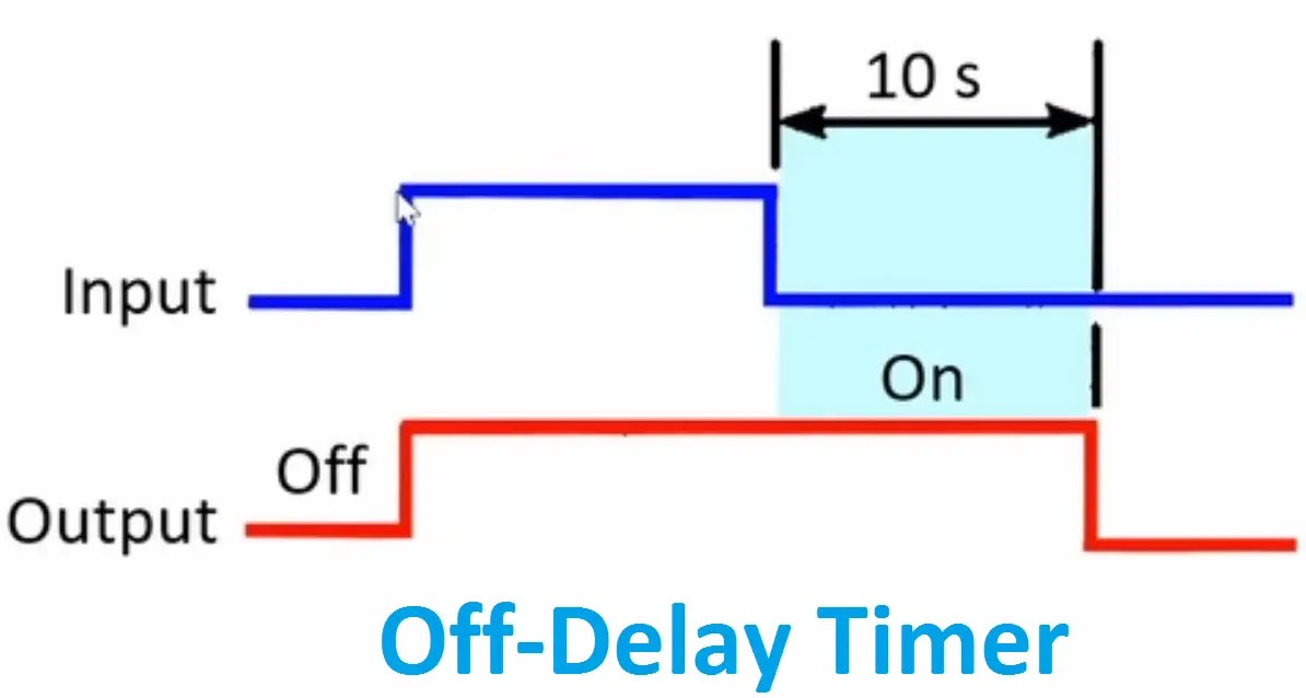
On Delay Timer Off Working Principle Electrical4u