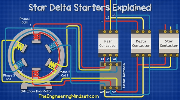
In the world of industrial automation, three-phase AC motor wiring diagrams are essential. For engineers and technicians who need to understand how a motor works, a wiring diagram is invaluable. Understanding how three-phase AC motors are wired allows workers to troubleshoot problems quickly and efficiently.
Three-phase AC motors use three alternating current (AC) phases that are 120 degrees out of phase with one another to generate power. The way the three phases are wired together has a direct effect on the motor's speed and power output. Depending on the configuration of the terminals inside the motor, a three-phase AC motor can be wired for full control of its speed, torque, and direction.
When wiring a three-phase AC motor, it is important to get the wiring correct. Visualizing the internal wiring of the motor and understanding how each of the three phases will interact with each other will ensure successful installation and operation. A three-phase AC motor wiring diagram provides the necessary information for technicians and engineers to accurately wire the motor and avoid costly errors.
When using a three-phase AC motor wiring diagram, there are several important points to remember. First, the motor's power supplies should be connected correctly. If the power supplies are not connected properly, the motor result in premature failure or poor performance. Next, it is important to consider the load and the motor specifications. The diagram should provide the complete wiring path, as well as all safety precautions. And finally, the terminals should be identified and labeled to make troubleshooting easier.
When working with three-phase AC motors, understanding the wiring diagrams is key. With a little patience and a good wiring diagram, engineers and technicians can tackle any installation project.
Electrical Electronic Systems Forward Reverse 3 Phase Ac Motor Control Wiring Diagram Star Delta Main Circuit 1 Mcb Mini Circut Breaker 2 Fc

How To Connect Three Phase Ac Motors Electronics360
Solved Figure 12 Shows The Wiring Diagram For Chegg Com

Ac Motor Types Working Principle Single Three Phase Motors

How To Use Three Phase Motor In Single Power Supply Electrical Engineering Centre

No 13 Winding Diagram For An Ac Motor Simulation Technology Electromechanical Design Jmag

In The Wiring Diagram Of A 9 Lead 230 460 Volt Three Phase Ac Squirrel Cage Induction Motor For Operation Six Connections Are Required Electrical Engineering Mcq Engineers Community

Vol Ii Alternating Cur Ac Motors Single Phase Induction

Three Phase Motors The Wiring Connection And Propelling Direction Hitachi Equipment Systems

Three Wire Vs Six Phase Motors Technical Articles

Difference Between Single Phase And Three Induction Motor All You Need To Know Manufacturing Blog Linquip
Single Phase Motor Connection Diagram And Wiring Procedure Etechnog

Induction Motor Protection System Circuit Diagram Working Globe

3 Phase Induction Motor Sd Controller Circuit Homemade Projects

3 Phase Motor Running On Single Power Supply Gohz Com

Schematic Diagram For Load Test On Three Phase Induction Motor Scientific

Basics Of 3 Phase Induction Motor Part 1

Single Phase Motor Connection With Magnetic Contactor Wiring Diagram Electrical And Electronics Technology Degree

Star Delta Starters Explained The Engineering Mindset


