With the increased use of electrical motor control diagrams circuits in everything from industrial settings to household appliances, it's important for individuals to understand the basics of these invaluable systems.
The primary purpose of an electrical motor control diagram is to provide a detailed guide of exactly how the motor should be powered and controlled. By following the instructions found in this diagram, you can guarantee that your motor not only runs properly, but also efficiently and safely.
At the heart of each motor control diagram lies the various electrical connections required to make the motor run. This includes the usage of things like contactors and relays, which help control the power to the motor as well as where it is applied. Additionally, there are protective components like switches, circuit breakers, and fuses that help protect the motor from any power surge or overload that might occur.
In order to fully understand how the motor works and all of its components, the electrical motor control diagram needs to be studied. Each component has its own purpose and they must be connected properly in order for the motor to run correctly. It's important to pay attention to where the wires are connected and note any discrepancies between the connection and the schematic layout to avoid any potential issues.
Lastly, understanding when it is time to upgrade or replace parts of the motor is essential in order to keep the motor running in peak condition. Checking the manual that comes with the motor should help in determining which parts need replacing or upgrading, and when it is necessary to do so.
In conclusion, the electrical motor control diagram is an integral part of any electric motor and learning how to read and follow the diagrams is crucial to both the safety and performance of the motor. Understanding the components and their purpose, studying the wiring layout, and knowing when to perform upgrades or replacements can all help ensure that your motor runs smoothly and safely for years to come.

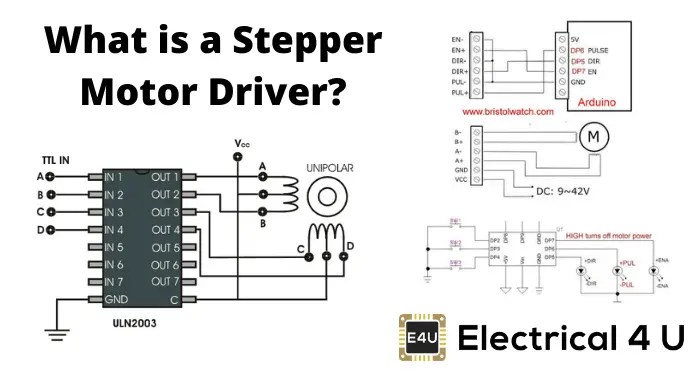
Stepper Motor Driver Circuit Diagram Schematic Electrical4u

Motor Control Circuits Diagram For Android

Motor Controller Electric Electrical Wires Cable Wiring Diagram Vehicle Png 760x536px

Electric Motors And Controls Training

Unit 17 Motor Control

Start Stop Circuit What They Are Where And How To Wire
Motor Control Circuit Diagram Learning Wiring 1 0 For Android

On Off Electric Motor Control Circuits Discrete System Elements Automation Textbook

Electrical Interlock Motor Control Forward Reverse Circuit Diagram Teknik Mekatronika

Main And Auxiliary Circuit Diagrams Of Switching Three Phase Motors Via Contactor Directly Eep

Ac Motor Sd Controller Circuit

Schematics And Wiring Diagrams Circuit 1

Variable Sd Electric Motor Bike Circuit Under Control Circuits 59008 Next Gr
Electrical Mechanical Info Forward Reverse Motor Control And Power Circuit Diagram Like Share Facebook

3 Simple Dc Motor Sd Controller Circuits Explained

The Principle Of Contactor Controlling Motor Forward Reverse Circuit

Control Basics Electric Motor Engineering Expert Witness Blog

Sd Control Methods Of Various Types Motors

Troubleshooting Pump Control Circuit Instrumentationtools
