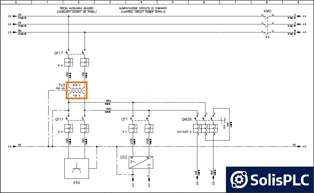
The intricate workings of an electrical circuit wiring diagram can seem overwhelming and confusing--but it doesn’t have to be. With a bit of knowledge and research, understanding how electrical circuits are wired and laid out can be relatively pain-free.
If you’re starting a home renovation or DIY project that involves electricity, being able to comprehend and use an electrical circuit wiring diagram is vital. That said, let’s take a look at the basics of wiring diagrams.
At its core, electrical circuit wiring diagrams show the path of electricity from one point to another and the components involved in the wiring setup. To create a wiring diagram, engineers first draw out the structural base, including all necessary components and then connect them as needed. The symbols associated with electrical components indicate what type of part it is and what it does. They also designate which wire goes where and what power source it’s connected to.
While they may seem daunting and strictly for technicians and engineers, electrical circuit wiring diagrams are extremely helpful for DIYers, too. If you’re not sure where to begin, check out online resources such as tutorials or even YouTube videos. It’s also highly recommended to speak with a knowledgeable professional before taking on a big electrical job. While you might be tempted to get stuck in right away, having someone on hand who’s experienced with wiring can make all the difference in the world.
When it comes to electrical circuit wiring diagrams, don’t be intimidated by the confusion. The best thing to do is take your time: research terminology, read resources, ask questions, and watch tutorials! If you’re prepared and organized, even the most complex wiring job can become a success.

Resources

What Is A Receptacle Wiring Diagram With Pictures

Resources

How To Construct Wiring Diagrams Controls

Operational Amplifier Electronic Circuit Wiring Diagram Stage Elements Angle Plan Gain Png Pngwing
What Is The Difference Between An Electrical Schematic Diagram And A Circuit Quora

Household Electric Circuits

Intro To Engineering Level 4 Electrical Diagrams

Wiring Diagram Background Vector Art Stock Images Depositphotos

Electrical And Electronic Drawing Controls

Electrical Panel Wiring Diagram
Electrical Engineering World 101 Wiring Diagram Pdf Link Free Https Bit Ly 2vakmfq Facebook

Relay Wiring Diagram Circuit Schematic Electronic Di Board Angle Electronics Png Pngegg

Simple Electric Circuit Basic Electrical Diagram Template

Light Switch Wiring Diagrams

How To Read Car Wiring Diagrams Short Beginners Version Rustyautos Com

Wiring Diagram Everything You Need To Know About

Electrical Outlet Wiring Diagram Radial And Ring Mains Electronics Engineering

Electrical Outlet Wiring Diagram Radial And Ring Mains Electronics Engineering
