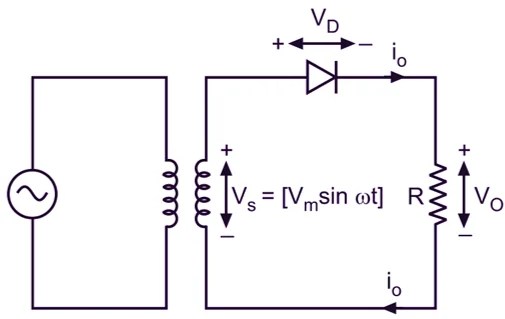
Are you looking for a better way to convert alternating current (AC) to direct current (DC)? Then a Rectifier Circuit Diagram could be the answer.
Using a rectifier circuit diagram is the most efficient and cost-effective way of converting AC power from sources like mains supplies into direct current power, which is needed for most modern electrical systems. A rectifier circuit can also be used to eliminate the adverse effects caused by alternating current such as electromagnetic interference from other devices.
A typical rectifier circuit diagram consists of two parts: the rectifier circuitry itself and the current transformers associated with the incoming power. The rectifier circuitry is responsible for transforming the alternating current into a direct current. It can also be used to regulate the amount of power available to the circuit, limiting it when required.
The second element is the current transformers associated with the incoming power. These are designed to make sure that the voltage and current being supplied to the rectifier circuitry is correct. This is achieved by ensuring that all of the power is converted from alternating to direct.
It’s important to understand how all of these elements fit together and how they work in order to ensure that the rectifier circuit is both reliable and efficient. This is why it's important to have access to a good circuit diagram so that the user can identify components and correctly interpret the connections being made.
Rectifier circuit diagrams are a great way to understand the flow of power in an electrical system. They provide a detailed understanding of the workings of the rectifier circuit and can provide insight into any problems that may exist.
Whether you are an experienced electrical engineer or a novice DIY enthusiast, having access to a quality rectifier circuit diagram is invaluable in making sure that your project runs smoothly and efficiently. If you are in the process of designing a new circuit or making repairs to an existing system, having a circuit diagram is essential.

Full Wave Rectifier Circuit Diagram Types Working Its Applications

What Is A Bridge Rectifier Powerversity Com

Bridge Rectifier

Full Wave Bridge Rectifier Circuit Diagram
Circuit060058 Design Tool Ti Com

Full Wave Bridge Rectifier With Capacitor Filter Design Calculation And Formula

Four Diode Full Wave Bridge Rectifier
How Is The Circut Diagram Of A Bridge Rectifier Which Converts Ac To Dc Quora

Bridge Rectifier Circuit Diagram 46 Off Www Aironeeditore It

Chapter3 Rectifier Filter And Regulator Visit For More

Circuit060009 Design Tool Ti Com

3 Phase Motorcycle Voltage Regulator Circuits Homemade Circuit Projects
Bridge Rectifier Circuit Diagram 46 Off Www Aironeeditore It

Single Phase Rectifier Circuit Diagram Working Types Waveforms Electricalworkbook

Bridge Rectifier Circuit Diagram Definition Efficiency Esaral

Bridge Rectifier Circuit Diagram Types Working Its Applications

What Is A Rectifier Block Diagram Working Principle Etechnog
Draw A Circuit Diagram Of Full Wave Rectifier Explain Its Working Principle Sarthaks Econnect Largest Online Education Community

Half And Full Wave Rectifier Working Principle Circuit Diagram
Circuitmix Com Simplified Circuit Diagram Of Arc Welding Machine What Would Happen If We Use A Half Wave Rectifier Instead Full Bridge Electrical Electricalengineering Electrician Electricalhacks Engineering Facebook

