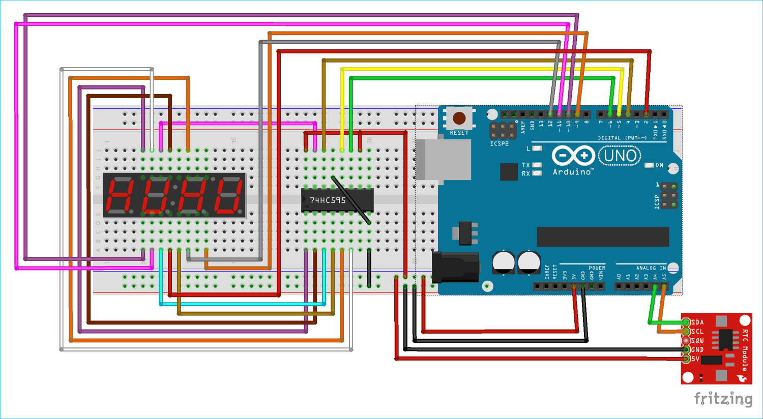
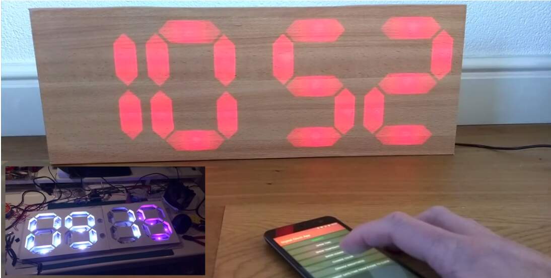
We all rely heavily on the convenience of digital clocks, from wall-mounted models that give us an update on the time of day to the clock on our phones and laptop screens. But what about the complex engineering behind these devices? A circuit diagram of a 7 segment digital clock provides a great example of the intricate workings of electronic technology.
At their core, digital clocks are powered by a simple concept: the ticking of time. To put this into action, a 7 segment digital clock requires a microprocessor, a control circuit, and a display unit. The microprocessor is responsible for counting each tick of the clock and then stores the result in memory. The control circuit uses this information to switch the display unit between 'on' and 'off' states, thus showing how much time has elapsed since the last signal was sent.
Now to get a little more technical. The 7 segment display is connected to the control circuit via a series of transistors and resistors. Each segment of the display is allocated a specific number of pins, which represent the binary value of each section. For example, the top left segment is assigned as '1', the top right as '2', and so on.
When the clock is powered up, the microprocessor begins counting each second until it reaches sixty. When the program reaches this point, the system of transistors and resistors determines the appropriate display segments to indicate 00:00. This sequence repeats, allowing the user to check the time accurately and conveniently.
The 7 segment display can be adapted to show any type of digital clock, from analogue designs to basic worded displays. It is a versatile and dependable form of technology, making it a popular choice for many applications across industries.
This circuit diagram is a prime example of the complexity yet elegant simplicity behind digital clocks. With the aid of electronics engineering, we are able to reap the benefits of accurate timekeeping - something that would otherwise take an enormous amount of effort and time manually. Thanks to this circuit diagram of a 7 segment digital clock, accurately telling the time is now just the click of a button away!

7 Segment Led Digital Clock With Ic Mm5314n Electronic Schematic Diagram

Arduino 7 Segment Display Clock Project By Multiplexing Four Displays

7 Segment Counter Using Ne555 And Cd4026

Digital Wall Clock On Pcb Using Avr Microcontroller Atmega16 And Ds3231 Rtc
How Can We Make A Digital Clock Using 7 Segment Display And Arduino Simulators Esp32 Raspberrypi Pico Quora

Forums Project Addition Or Changes Adjule Resetable Digital Alarm Clock Using 8051 89s52 89c52 In 7 Segment Display Rickey S World Of Microcontrollers Microprocessors

12h 24h Digital Clock Circuit Online Electronics Course

Simple Digital Clock Using Lm8650 Ic Circuit Homemade Projects

Digital Clock Circuit Using Ic 555 And 4026 Diy Electronics Projects

Seven Segment Based Alarm Clock Using 8051 Microcontroller At89c51

Diy 7 Segment Digital Clock Eeweb

Bcd To 7 Segment Display
Github Ashvnv 8051 Digitalclock Rtc 24hr Digital Clock Using And Ds1307

Print Adc Value On 7 Segment Display Using Pic Microcontroller

8051 Digital Clock On 7 Segment Non Multiplexed Micro

7 Segment Led Counter Circuit Diagram And Instructions

Display 7 Segment Youe

7 Segment Mini Clock Using Pic16f628a And Ds1307 Rtc Electronics Lab Com
Digital Clock Using Seven Segment Displays With Arduino