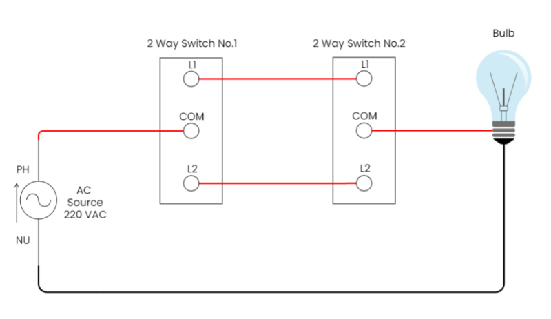
The world of electronics can be intimidating, but with a basic understanding of circuit diagrams, the mystery begins to unravel. A circuit diagram, or schematic, is a visual representation of an electrical system. It shows the components and connections in an organized manner, allowing electricians and engineers to troubleshoot problems and make modifications efficiently and safely.
Most circuits have several components, such as resistors, capacitors, transistors, integrated circuits, and power sources. Each component is represented by a specific symbol on the schematic, making it easy to identify and interpret the design. Lines connecting the symbols represent the wiring carrying electricity from one component to another.
Electrical engineers use different types of diagrams to represent various electronic circuits. The most common type is the line diagram, which identifies all of the components and their connectivity. Next, the ladder diagram shows how the components are arranged in a more linear fashion, while the functional block diagram combines individual components into larger modules or blocks that work together to form a larger system.
Circuit diagrams are essential for anyone working with electronics, providing invaluable information on how a system works. They can help electricians prevent mistakes during installation, determine the source of a malfunction, and develop new designs and improvements.
At the same time, circuit diagrams can also serve as teaching tools for students who are trying to understand the fundamentals of electricity and electronics. By closely studying these diagrams, students can learn about how different components interact, internal design principles, useful circuit shortcuts, and safety practices.
Whether you're an experienced professional, a budding student, or someone tinkering with their first electronics project, circuit diagrams are a must-have resource. A good understanding of these diagrams can make all the difference when it comes to a successful electrical system.

How To Read A Schematic Learn Sparkfun Com

Examples Of Electronic Schematic Diagrams

How To Read A Schematic Learn Sparkfun Com

How To Read A Schematic Learn Sparkfun Com

Difference Between Pictorial And Schematic Diagrams Lucidchart Blog
:max_bytes(150000):strip_icc()/kr7ysztofwiringdiagram-5c4df148c9e77c0001f32271.jpg?strip=all)
What Is A Schematic Diagram

Electric Circuit Diagrams Lesson For Kids Transcript Study Com

How To Read A Schematic Learn Sparkfun Com

Electric Circuit Diagram Images Browse 17 972 Stock Photos Vectors And Adobe
:max_bytes(150000):strip_icc()/EakachaiLeesin-EyeEm-manufacturingschematic-5c4df19b46e0fb0001a8e7df.jpg?strip=all)
What Is A Schematic Diagram

Wiring Diagram A Comprehensive Guide Edrawmax Online

How To Read A Schematic Learn Sparkfun Com

Circuit Diagrams Tutorial Electronics Diagram General Theory Tutorials Circuits Hobby Projects

Circuit Diagram Of The Model Diffe Sections Schematic Scientific
Simple Switched Supply Circuit Diagram

Series And Parallel Dc Circuits Explained Examples Included Electrical4u

Drawing Circuits For Kids Physics Lessons Primary Science

How To Read A Circuit Diagram Archives Upmation